How can I use the Summation Function in PTW ?
The Protective Device Function in PTW v6.5 contains new features for modeling additional functions, such as summation, that can be utilized in Arc Flash Evaluation. The following provides a brief description of implemented concept for the summation function, how it can be used, and how to apply it in a study.
General Implemented Concept
- The summation function in PTW is similar to a bus differential which can sum up the SC contribution currents vectors (magnitude and angle) caused by a fault and passed through multiple devices already modeled in the connected branches to the fault location.
- Since the actual CTs for sensing and the conversion of the fault currents are not yet available, the protective devices available in each branch will act in place of the CTs and the program will internally account for the SC current summation.
- The actual characteristics of the bus differential relay cannot currently be modeled in Captor. However, a generic TCC representing any adjustable pickup and delay can be used instead to represent the trip time for the fault.
- Based on the above, a protective device is needed to be inserted in each of the branches connected to the bus as the location of fault to define the protected zone. Every device type needs to be set as Summation through the Function button in Captor or the Component Editor and linked to the library to represent the generic TCC of the device.
The following example will better describe the use and application of the summation function.
Example
Figures 1 and 2 represent a sample dual source distribution system containing only the phase Over Current Type Function while Figure 3 displays the arc flash results for the switchgear bus (BUS-SWG) connecting the generators and motor loads without any summation function or bus differential.
The following steps can be used to add summation function to the existing overcurrent phase function of the PD-GEN-1 relay. This relay will be used together with all other relays (PD-GEN-2, PD-1, and PD-2) as the reference for the sensed current by each of these CTs.
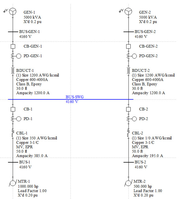
Figure 1
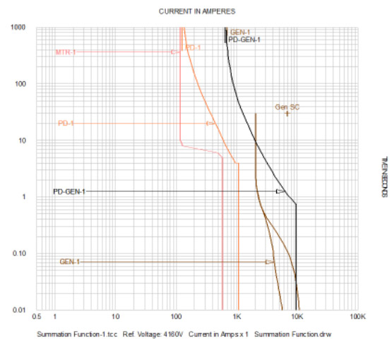
Figure 2
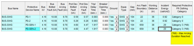
Figure 3
- Select the PD-GEN-1 device in the Captor TCC drwing (Figure 4) then click the Function button to display the Protection Functions.
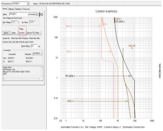
Figure 4 - Click the New button and type in Summation under the Function Name column. Select Summation from the Type pull-down menu (Figure 5).
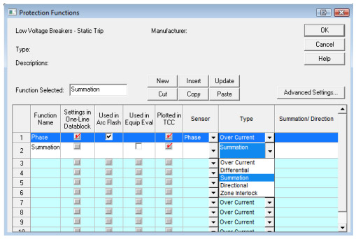
Figure 5 - The window for "Summation of Current from Selected Devices" will prompt for the selection of the protective devices as the reference CTs. An additional option is provided to select these devices from the TCC associated one-line drawing or from all of the devices in the project (Figure 6).
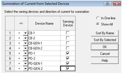
Figure 6 - Select and check the box for PD-GEN-1, PD-GEN-2, PD-1, and PD-2 as sensing devices. Note that there is a +/- drop down menu for each device to reverse the direction of the sensed current. In other words, it will add a 180 deg to the phase angle of the sensed current vector. Leave the +/- drop-down menu as "+" and click OK to have the referenced device currents summed and displayed under the Summation/Direction column (Figure 6 and 7).
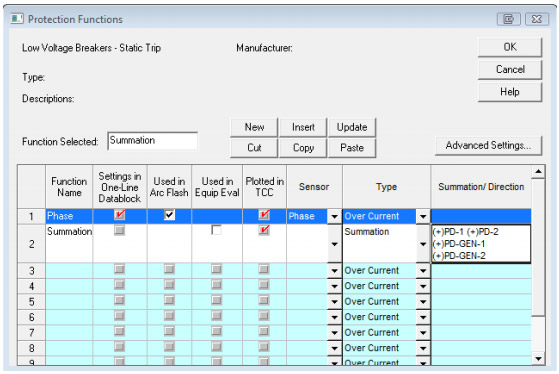
Figure 7 - Note that the check box for "Used in Arc Flash" is not available for the newly created differential function because no TCC curve from the library is assigned to it at this point. Click OK to return to the Captor TCC screen to link this function to a model from the library.
- Once the summation is displayed on top of the Functions button, click the Library button to select a generic model for this differential function, similar to the device in Figure 8. Click Apply and Close to review the TCC of the new differential function in Captor.
- Note that the function names (Phase or Summation) are now added at the end of the PD-GEN-1 device name (Figure 9).
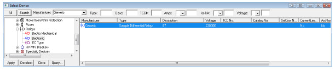
Figure 8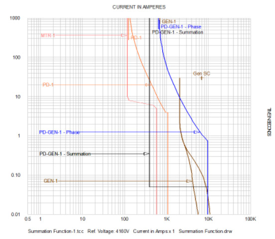
Figure 9 - Click the Function button again to confirm that the "Used in Arc Flash" is now available for the summation function as well. Check this box to use the summation function in Arc Flash. Note that the box in front of Phase is automatically unchecked (Figure 10). Now click OK.
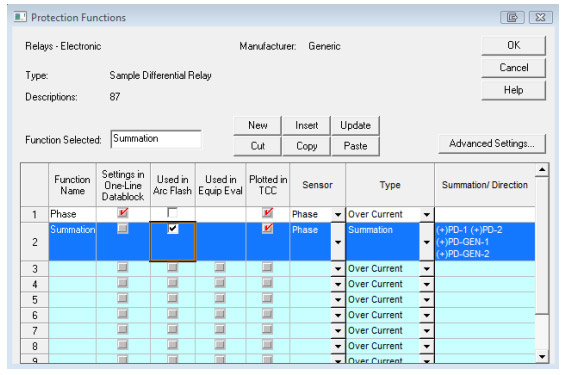
Figure 10 - Repeat steps 1 through 8 above for all for other devices that are expected to isolate the protected zone. They would be PD-GEN-2, PD-1, and PD-2 in our sample case.
- Select BUS-SWG from the one-line drawing. Right-click and choose Go To/Find > Go To Arc Flash to analyze the study results for the bus which is within the protection zone of summation relays (Figure 11).
- As shown in Figure 12, the incident energy and required PPE has been reduced due to 0.05 sec trip time of the summation functions set at this delay time.
- Note that in the sample case, the addition of summation function to the motor protection devices (PD-1 and PD-2) will not change the arc flash study results for BUS-SWGC. This is due to having a total of 0.083 sec (5 cycle) duration for the contribution of the motors that is less than total clearing time of summation function for these devices PD-1 and PD-2 Summation Function Total Clearing Time = 0.05 + 0.083 = 0.135 sec > 0.083 sec (5 cycle)
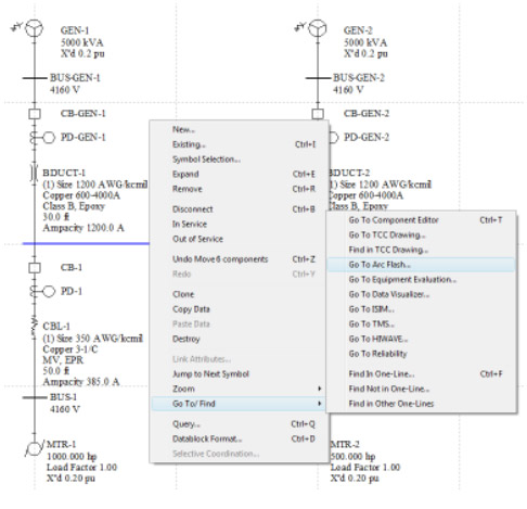
Figure 11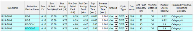
Figure 12