Arc Flash Evaluation using IEEE 1584-2018
PTW Arc Flash Evaluation calculates the incident energy and arc flash boundary for each location in a power system. Arc Flash saves time by automatically determining trip times from the protective device settings and arcing fault current values. Incident energy and arc flash boundaries are calculated following the NFPA 70E, IEEE 1584 and NESC standards. Clothing requirements are specified from a user-defined clothing library. Clearing times can be automatically reduced based on current-limiting capabilities.
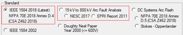
Starting with the Power*Tools for Windows V8.0.3.3 Release, the Arc Flash Evaluation module has been updated to include the IEEE 1584-2018 standard. This guide utilizes similar parameters as IEEE 1584-2002, with the addition of bus bar configurations and box enclosure dimensions:Busbar Config
Electrode configuration of the equipment in which 5 types can be chosen from:
• VCB – Vertical electrodes inside a metal box enclosure.
• VCBB – Vertical electrodes terminated in a barrier inside a metal box enclosure.
• HCB – Horizontal electrodes inside a metal box enclosure.
• VOA – Vertical electrodes in open air.
• HOA – Horizontal electrodes in open air.
Note: Refer to the standard for guidance on classification of the electrode configurations.
Box Width / Height / Depth
The dimensions of the metal box enclosure for VCB, VCBB, and HCB
electrode configurations. Unlink the field if custom dimensions
are to be entered. Shallow depth are <= 8in. Typical
dimensions are selected based on the bus voltage and equipment
type. See Table 7 of the standard for typical enclosure
sizes.
The range of the model, methodology, and arc flash equations are mostly
different from the previous version. Refer to IEEE 1584-2018
for comprehensive details.
For systems outside the IEEE 1584-2018 range of model, the Ralph Lee equation will generally be used.
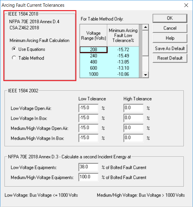
There are two calculations conducted in the software: one with the
average arcing current and another with a minimum arcing current.
Set the lower bound tolerance for the minimum arcing current in the
Arcing Fault Current Tolerances option. The highest incident
energy between the two arcing currents will be the one reported in the
Arc Flash table.
The PPE is determined based on the calculated Incident Energy and the user definable Personnel Protection Equipment Table.
To purchase a copy of IEEE 1584-2018, visit: https://standards.ieee.org/develop/project/1584.html