Off-nominal Transformer Tap Settings
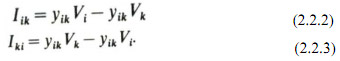
A transformer with turns ratio a interconnecting two nodes i, k can be represented by an ideal transformer in series with the nominal transformer leakage admittance as shown in Fig. 2.2 (a). If the transformer is on nominal tap (a=1), the nodal equations for the network branch in the per unit system are
In this case Iik=-Iki*
For an off-nominal tap setting and letting the voltage on the k side of the ideal transformer be Vt we can write
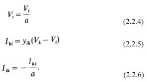
Eliminating Vt between equations (2.2.4) and (2.2.5) we obtain
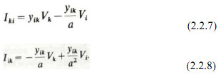
A simple equivalent - circuit can be deduced from equations (2.2.7) and (2.2.8) the elements of which can be incorporated into the admittance matrix. This circuit is illustrated in Fig. 2.2(b). The equivalent circuit of Fig 2.2(b) has to be used with care in banks containing delta-connected windings. In a star-delta bank of single-phase transformer units, for example, with nominal turns ratio, a value of 1.0 per unit voltage on each leg of the star winding produces under balanced conditions 1.732 per unit voltage on each leg of the delta winding (rated line to neutral voltage as base). The structure of the bank requires in the per unit representation an effective tapping at √3 nominal turns ratio on the delta side, i.e. a= 1.732.
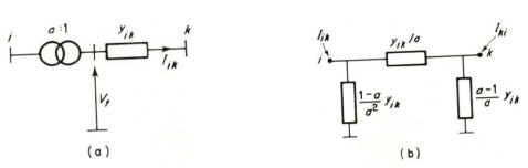
Figure 2.2
Transformer with off-nominal tap setting
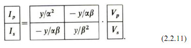
For a delta-delta or star-delta transformer with taps on the star winding, the equivalent circuit of Fig. 2.2(b) would have to be modified to allow for effective taps to be represented on each side. The equivalent-circuit model of the single-phase unit can be derived by considering a delta-delta transformer as comprising a delta-star transformer connected in series (back to back) via a zeroimpedance link to a star-delta transformer, i.e. star windings in series. Both neutrals are solidly earthed. The leakage impedance of each transformer would be half the impedance of the equivalent delta-delta transformer. An equivalent per unit representation of this coupling is shown in Fig. 2.3. Solving this circuit for terminal currents
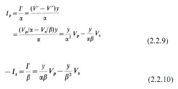
or in matrix form
These admittance parameters form the primitive network for the coupling between a primary and secondary coil.
Phase-shifting Transformers
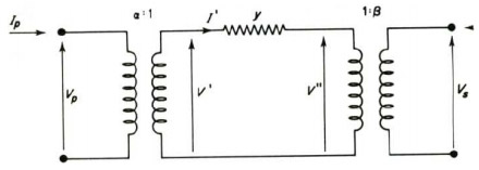
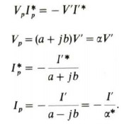
Figure 2.3
Basic equivalent circuit in p.u. for coupling between primary and secondary coils with both primary and secondary off-nominal tap ratios of α and β
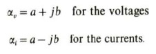
To cope with phase shifting, the transformer of Fig. 2.3 has to be provided with a complex turns ratio. Moreover, the invariance of the product VI* across the ideal transformer requires a distinction to be made between the turns ratios for current and voltage, i.e.
or
Thus the circuit of Fig. 2.3 has two different turns ratios, i.e.
and
Solving the modified circuit for terminal currents.
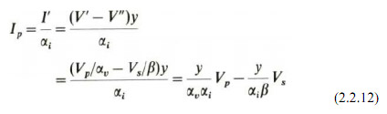
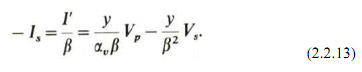
Thus, the general single-phase admittance of a transformer including phase shifting is
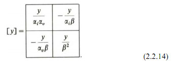
Note that, although an equivalent lattice network similar to that in Fig. 2.3 could be constructed, it is no longer a bilinear network as can be seen from the asymmetry of y in equation (2.2.14). The equivalent circuit of a single-phase phase-shifting transformer is thus of limited value and the transformer is best represented analytically be its admittance matrix.