How can I use the Directional Function in PTW?
The Protective Device Function in PTW v6.5 contains new features for modeling additional functions, such as directional, that can be utilized in Captor and Arc Flash Evaluation. The directional functions of the devices can be found in several relays in the Captor Library. The following provides a brief description of implemented concept for the directional function, how it can be used, and how to apply it in a study.
General Implemented Concept
- The directional function in PTW can detect the direction of short-circuit current caused by a fault and passed through a protective device modeled in the system.
- Since the actual CT and VT for sensing and determining the fault current directions are not yet available, the user needs to define the sensed direction of current through the selection of "From Device" and "To Device" in the Advanced Settings of the Protection Functions window.
- The directional functions of the protective devices are normally similar to overcurrent functions and the model for such devices can be found in several relays of the Captor Library.
- The interlock between multiple trips and interrupting units are not yet available. Therefore each device needs to be modeled separately using the directional function by selecting the From and To Device as the reference for the sensed fault current.
The following example will better describe the use and application of the directional function.
Example
Figures 1 and 2 represents a dual source distribution system containing only the phase Over Current Type Function while Figure 3 displays the arc flash results for switchgear bus (BUS-GEN) connecting the generator to the cable which in turn is feeding the BUS-SWG-1 section without any directional function. Note that the PD-GEN-2 is not linked to the Captor Library to represent an actual protective device but will be used for isolation of the directional fault later in this FAQ.
The following steps can be used to add a directional function to the existing overcurrent phase function of the PD-GEN-1 relay. PD-GEN-1 will be used together with PD-GEN-2 for direction detection and isolation of the fault current.
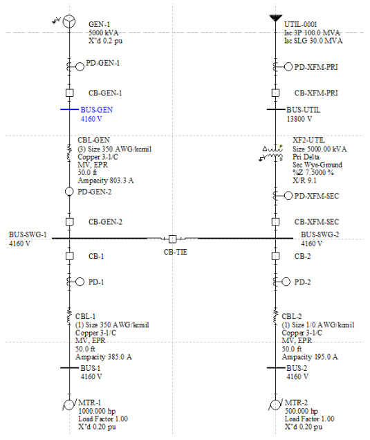
Figure 1
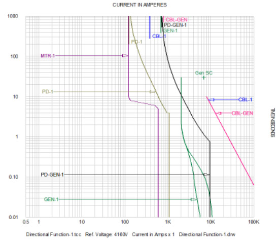
Figure 2
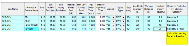
Figure 3
- Select the PD-GEN-1 device in the Captor TCC drawing (Figure 4) and click the Function button to display the Protection Functions.
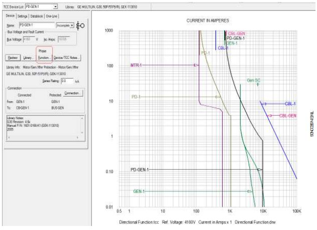
Figure 4 - Click the New button and type in Directional under the Function Name column. Select Directional from the Type pull-down menu (Figure 5).
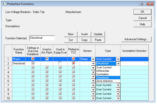
Figure 5 - The window for "Direction of Fault Current" will prompt with "From Device" and "To Device" for the selection of the components to determine the direction of fault that would cause the protective device to trip. The drop down menu under each of these fields will show the components connected to both ends of the selected device. In our case, they are GEN-1 and BUS-GEN (Figure 6).
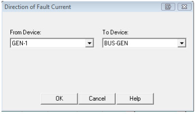
Figure 6 - Select GEN-1 (generator) as the "From Device" and BUS-GEN as the "To Device" and click OK. The referenced direction of the sensed currents will be displayed with "(->) symbol under Summation/Direction column (Figure 6 and 7).
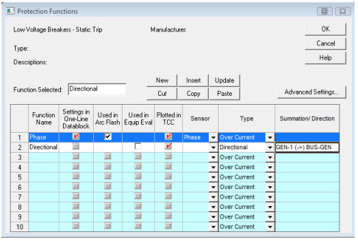
Figure 7 - Note that the check box for "Used in Arc Flash" is not available for the newly created directional function because no TCC curve from the library is assigned to it at this point. Click OK to return to the Captor TCC screen to link this function to a model from the library.
- Once the directional is displayed on top of the Functions button, click the Library button to select a model for this directional function, similar to the device in Figure 8. Click Apply and Close.
- Note that the function names (Phase or Directional) are now added to the end of the PD-GEN-1 device name. In our sample case, the Definite Time is selected as the delay time for the directional (67) function (Figure 9).
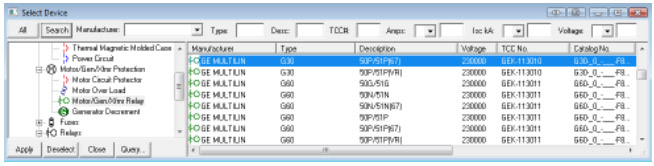
Figure 8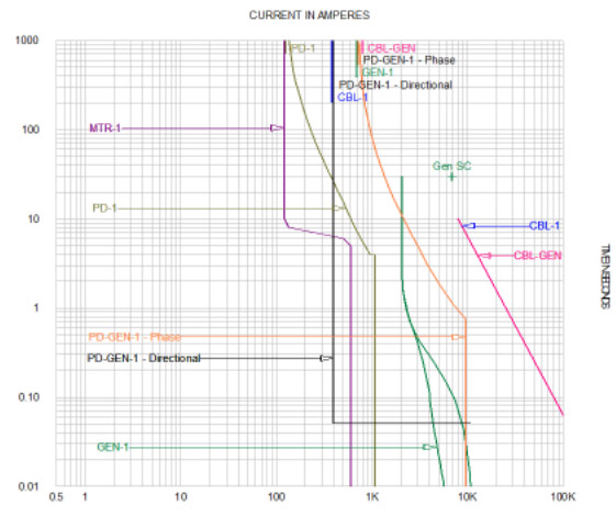
Figure 9 - Click the Function button again to confirm that the "Used in Arc Flash" is now available for directional function as well. Check this box to use the directional function in Arc Flash. Note that the box in front of Phase is automatically unchecked (Figure 10). Now click OK.
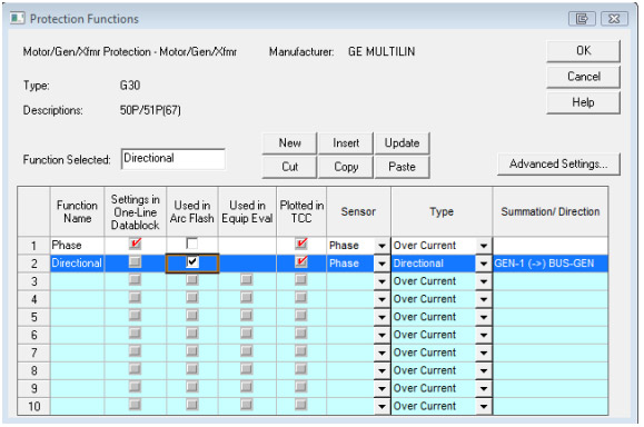
Figure 10 - Repeat steps 1 through 8 for other devices expected to isolate the protected zone. PD-GEN-2 is used in our sample case
- Select BUS-GEN from the one-line drawing. Right-click and choose Go To/Find > Go To Arc Flash to analyze the study results for the bus which is within the protection zone of the directional relays (Figure 11).
- As shown in Figure 12, the incident energy and required PPE has been reduced due to the 0.05 sec trip time of the directional functions set at this delay time. The *N17 note confirms that the directional function has operated and interrupted the arc.
- If the direction of the fault is not compatible with the selected direction in the directional function, then the Arc Flash study results will show the "(*N18) - Directional Function DID NOT Operate.Prot Dev Arcing Fault is not reported" note. This note indicates that the arcing fault was not interrupted by the directional function and therefore no arcing fault current is displayed for this device. An example is displayed in Figure 13.
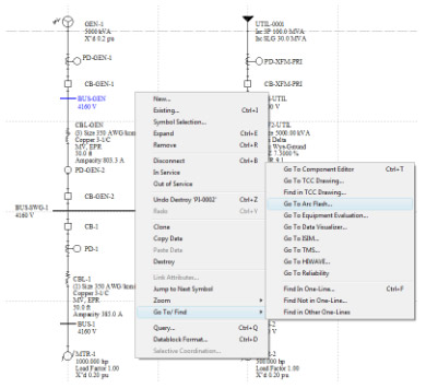
Figure 11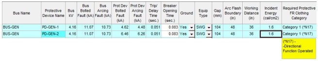
Figure 12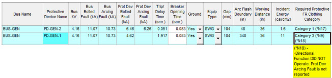
Figure 13