Three ways of showing Fault Current in the TCC:
Within the Device tab for TCC drawings, the Isc Amps field indicates the total fault current on the connected bus. In terms of TCC drawings, this value determines the maximum current where the device's curve will be cut off.
There are three ways to show the maximum available fault current seen by a protective device. Start by selecting Settings menu > TCC Settings > Fault Current tab
1. Study Result:
This will link the available fault current to the short circuit study result. When selected, this option will gray out the Isc Amps field in the TCC Device tab.
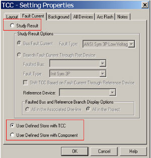
There are two User Defined options:
2.) User Defined Store with TCC
With this option, the Isc Amps for a particular device is saved in the TCC drawing. You may place the same protective device in multiple TCC drawings and use different Isc Amps each time.
3.) User Defined Store with Component
With this option, the Isc Amps set for a particular device in a TCC drawing will be used for other TCC drawings if this option is selected again.
Note: Phase and ground functions have the same fault current (Isc Amps).