Overcurrent Coordination Basics Motors |
||
| The information presented in this application guide is for review, approval, interpretation and application by a registered professional engineer only. SKM disclaims any responsibility and liability resulting from the use and interpretation of this information. Reproduction of this material is permitted provided proper acknowledgement is given to SKM Systems Analysis Inc. Purpose The purpose of this guide is to provide a basic overcurrent protection philosophy for motors. |
||
| MV Motor Overcurrent Protection Time-current curve (TCC) landmarks (figure 1) |
||
| • Full load amps – located in the upper decade • Starting time – located in the middle decades • Locked rotor amps – located in the lowest decade • Motor starting curve – located in all 5 decades • Stator damage curve – located in the upper decade • Rotor damage curve – located in the middle decades |
||
| TCC regions (figure 2) | ||
| • Equipment operating region – located at and to the left of the motor starting curve • Equipment damage region – located to the right and above the damage curves • Protective device operating region – located between the equipment operating and damage regions |
||
| Suggested overcurrent protection (figure 3) | ||
| • Set protection above the motor starting curve • Set protection below the damage curves |
||
| Comments | ||
| • If the motor is allowed to operate at locked rotor for a time at or above the locked rotor limit curve, rotor damage will occur. • If current penetrates the limits of the stator overload limit curve, insulation life is reduced. |
||
 |
||
| Fig. 1 MV motor TCC landmarks | ||
 |
||
| Fig. 2 MV motor TCC region | ||
 |
||
| Fig. 3 MV motor overcurrent protection | ||
| LV Motor Overcurrent Protection TCC landmarks (figure 4) |
||
| • Full load amps – located in the upper decade • Starting time – located in the middle decades • Locked rotor amps – located in the lowest decade • Motor starting curve – located in all 5 decades • Rotor hot stall point – located in the upper middle decades |
||
| TCC regions (figure 5) | ||
| • Equipment operating region – located at and to the left of the motor starting curve • Equipment damage region – located to the right and above the rotor hot stall point • Protective device operating region – located between the equipment operating and damage regions |
||
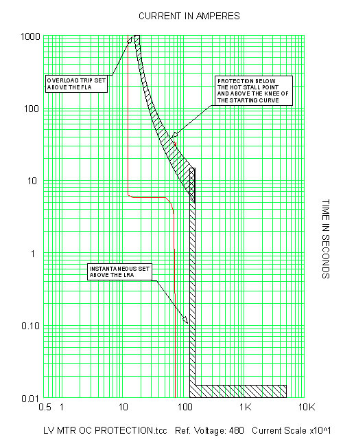
| Suggested overcurrent protection (figure 6) | ||
| • Set protection above the motor starting curve • Set protection below the hot stall point |
||
| Comments | ||
| • If the motor is allowed to operate at locked rotor for a time at or above the hot stall point, rotor damage will occur. | ||
 |
||
| Fig. 4 LV motor TCC landmarks | ||
 |
||
| Fig. 5 LV motor TCC regions | ||
 |
||
| Fig. 6 LV motor overcurrent protection | ||
| References | ||
| • Other Application Guides offered by SKM Systems Analysis at www.skm.com • Electrical Transmission and Distribution Reference Book, ABB Power T&D Company, Raleigh, North Carolina, 1997 • Protective Relaying Theory and Applications, 2nd Edition, Marcel Dekker, New York, 2004 |
||
| The latest revision of: | ||
| • IEEE Std 242, IEEE Recommended Practice for Protection and Coordination of Industrial and Commercial Power Systems (IEEE Buff Book) • IEEE Std 620, IEEE Guide for the Presentation of Thermal Limit Curve for Squirrel Cage Induction Machines • IEEE Std C37.96, IEEE Guide for AC Motor Protection • NEMA Std MG-1, Motors and Generators |
||
| back to Application guides | ||