Overcurrent Coordination Basics Conductors |
||
| The information presented in this application guide is for review, approval, interpretation and application by a registered professional engineer only. SKM disclaims any responsibility and liability resulting from the use and interpretation of this information. Reproduction of this material is permitted provided proper acknowledgement is given to SKM Systems Analysis Inc. Purpose The purpose of this guide is to provide a basic overcurrent protection philosophy for conductors. |
||
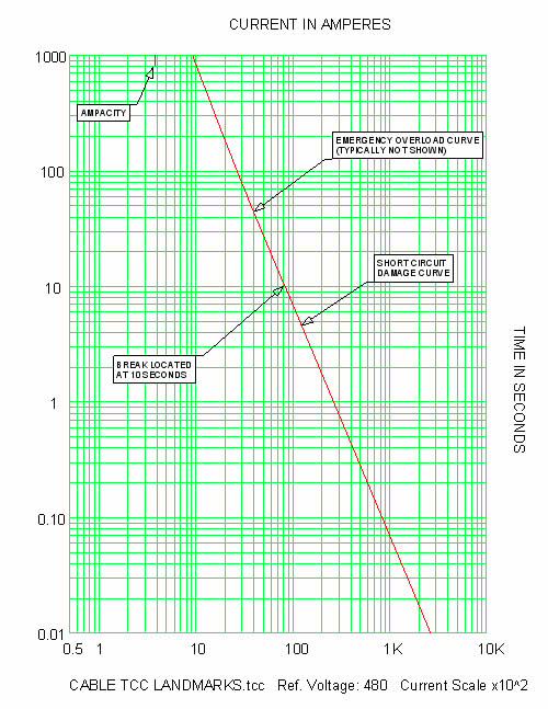
| Cable Overcurrent Protection Time-current curve (TCC) landmarks (figure 1) |
||
| • Ampacity – located in the upper decade • Emergency overload curve – located in the upper 2 decades, typically not shown • Short circuit damage curve – located in the bottom 3 decades |
||
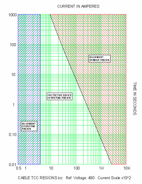
| TCC regions (figure 2) | ||
| • Equipment operating region – located at and to the left of the ampacity • Equipment damage region – located to the right and above the damage curves • Protective device operating region – located between the equipment operating and damage regions |
||
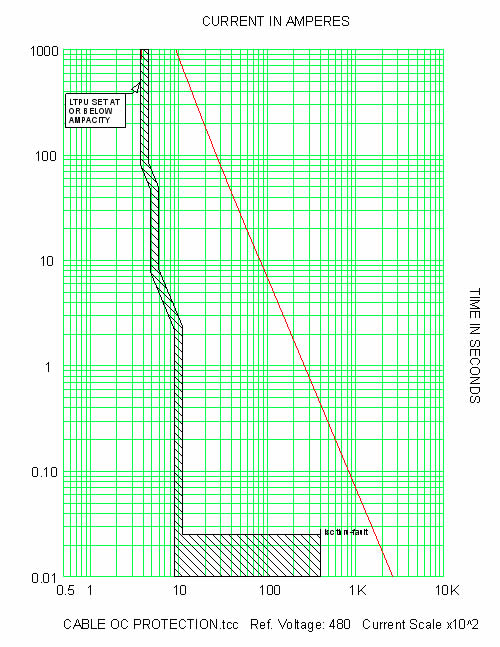
| Suggested overcurrent protection (figure 3) | ||
| • Set device long time pickup (LTPU) function at or below the ampacity • Set all other device functions at or below the damage curves |
||
| Comments | ||
| • If current penetrates the limits of the thermal overload curve, cable insulation life is reduced. • If the maximum through-fault current penetrates the limits of the short circuit damage curve, cable insulation will be damaged. The through-fault current is defined as the maximum current that can flow for a fault at the load-side terminals of the feeder. |
||
 |
||
| Fig. 1 Cable TCC landmarks | ||
 |
||
| Fig. 2 Cable TCC regions | ||
 |
||
| Fig. 3 Cable overcurrent protection | ||
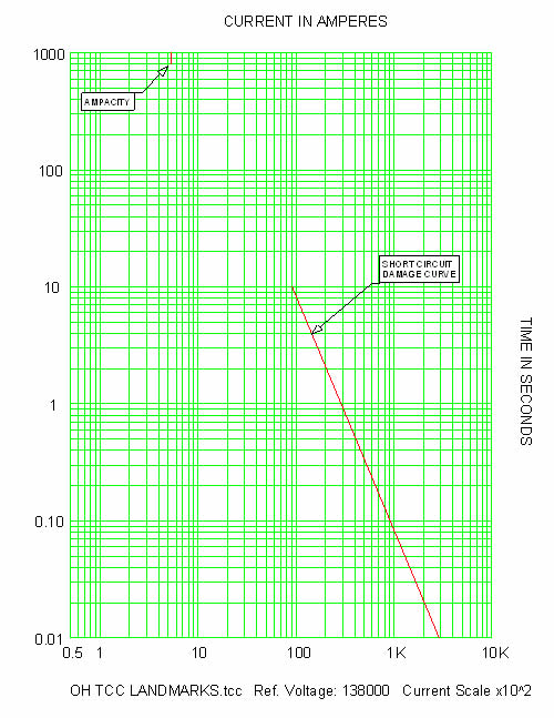
| OH Conductor Overcurrent Protection TCC landmarks (figure 4) |
||
| • Ampacity – located in the upper decade • Short Circuit Damage Curve – located in the bottom 3 decades |
||
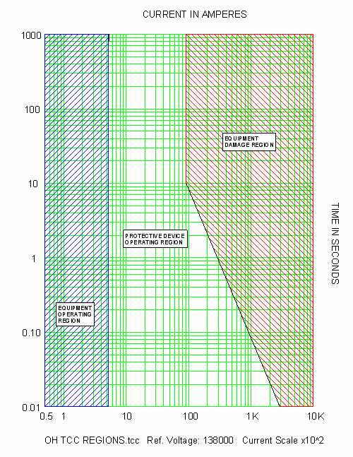
| TCC regions (figure 5) | ||
| • Equipment operating region – located at and to the left of the ampacity • Equipment damage region – located to the right and above the damage curve • Protective device operating region – located between the equipment operating and damage regions |
||
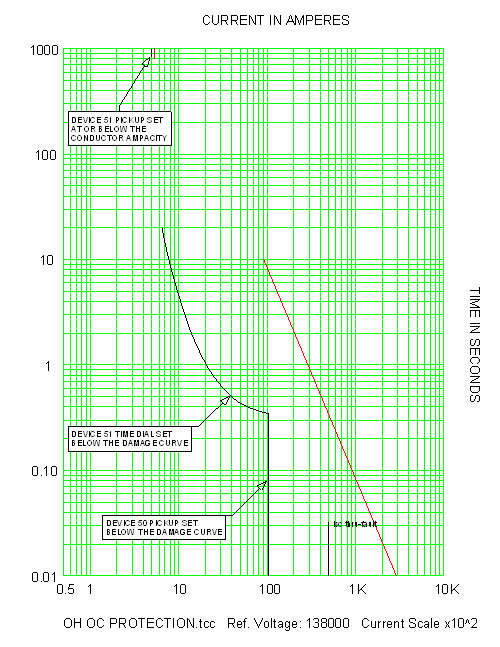
| Suggested overcurrent protection (figure 6) | ||
| • Set device long time pickup (LTPU) function at or below the ampacity • Set all other device functions below the damage region |
||
| Comments | ||
| • If the maximum through-fault current penetrates the limits of the short circuit damage curve, conductor damage will occur. The through-fault current is defined as the maximum current that can flow for a fault at the load-side terminals of the conductor. |
||
 |
||
| Fig. 4 OH conductor TCC landmarks | ||
 |
||
| Fig. 5 OH conductor TCC regions | ||
 |
||
| Fig. 6 OH conductor overcurrent protection | ||
| References | ||
| • Other Application Guides offered by SKM Systems Analysis at www.skm.com • Aluminum Electrical Conductor Handbook, The Aluminum Association Inc., Washington, D.C., 3rd edition, 1989 • Electrical Transmission and Distribution Reference Book, ABB Power T&D Company, Raleigh, North Carolina, 1997 • Protective Relaying Theory and Applications, 2nd Edition, Marcel Dekker, New York, 2004 |
||
| The latest revision of: | ||
| • IEEE Std 242, IEEE Recommended Practice for Protection and Coordination of Industrial and Commercial Power Systems (IEEE Buff Book) • IEEE Std C37.113, IEEE Guide for Protective Relay Applications to Transmission Lines |
||
| back to Application guides | ||