Overcurrent Coordination Basics Capacitors |
||
| The information presented in this application guide is for review, approval, interpretation and application by a registered professional engineer only. SKM disclaims any responsibility and liability resulting from the use and interpretation of this information. Reproduction of this material is permitted provided proper acknowledgement is given to SKM Systems Analysis In Purpose The purpose of this guide is to provide a basic overcurrent protection philosophy for capacitors. |
||
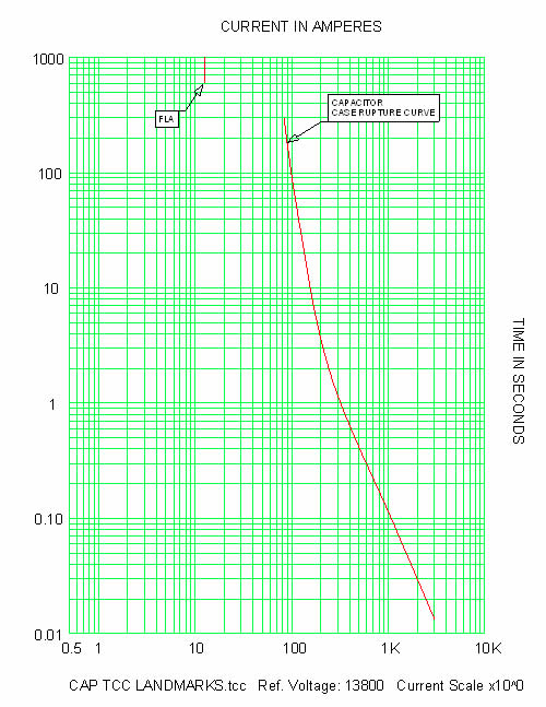
| Transformer Overcurrent Protection Time-current curve (TCC) landmarks (figure 1) |
||
| • Full load amps (FLA) – located in the upper decade • Case rupture curve – located in all 5 decades |
||
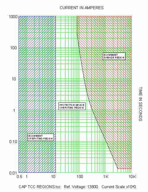
| TCC regions (figure 2) | ||
| • Equipment operating region – located at and to the left of the FLA marker • Equipment damage region – located to the right and above the case rupture curve • Protective device operating region – located between the equipment operating and damage regions |
||
| Suggested overcurrent protection (figure 3) | ||
| • Set protection above the full load amps • Set protection below the case rupture curve |
||
| Comments | ||
| • If current penetrates the limits of the case rupture curve, the capacitor enclosure will fail. Failure of the enclosure will cause a discharge of liquid and may cause damage to adjacent capacitor units. | ||
 |
||
| Fig. 1 Capacitor TCC landmarks | ||
 |
||
| Fig. 2 Capacitor TCC regions | ||
 |
||
| Fig. 3 Capacitor overcurrent protection | ||
| References | ||
| • Other Application Guides offered by SKM Systems Analysis at www.skm.com • Electrical Transmission and Distribution Reference Book, ABB Power T&D Company, Raleigh, North Carolina, 1997. |
||
| The latest revision of: | ||
| • IEEE Std C37.99, IEEE Guide for the Protection of Shunt Capacitor Banks • IEEE Std 18, IEEE Standard for Shunt Power Capacitors • IEEE Std 1036, IEEE Guide for the Application of Shunt Power Capacitors • NEMA Std CP-1, Shunt Capacitors |
||
| back to Application guides | ||