Equipment Damage Curves Transformers |
||||||||||||||||||||||||||||||||||||||||||||||||||||||||||||||||||||||||
| The information presented in this application guide is for review, approval, interpretation and application by a registered professional engineer only. SKM disclaims any responsibility and liability resulting from the use and interpretation of this information. Reproduction of this material is permitted provided proper acknowledgement is given to SKM Systems Analysis Inc. Purpose The purpose of this guide is to provide basic information about transformer through-fault damage curves and characteristic landmarks necessary for plotting on time-current curves, for the purpose of equipment overcurrent protection. Damage curves are defined in the IEEE standards in per unit on the nominal base rating (kVA) of the transformer, and are not adjusted with changes to the core, winding material or method of cooling. Full Load Amps (FLA) FLA is the rated continuous current carrying capacity of a transformer at a referenced ambient temperature and allowable temperature rise, see table 1. The FLA label is located on a time-current curve (TCC) in top decade at 1000 seconds. The total temperature rise of an OA 65°C transformer, at an average/maximum ambient temperature of 30/40°C, is 110/120°C. These temperatures do exceed the transformer insulation rating of 105°C, and are allowed by the standards. |
||||||||||||||||||||||||||||||||||||||||||||||||||||||||||||||||||||||||
| Table 1 Transformer temperature ratings | ||||||||||||||||||||||||||||||||||||||||||||||||||||||||||||||||||||||||
|
||||||||||||||||||||||||||||||||||||||||||||||||||||||||||||||||||||||||
| SC Withstand Capability (Damage) Curves ANSI C57.109 defines damage characteristics for oil-filled, power transformers see tables 2-5. ANSI C57.12.59 defines damage characteristics for dry-type transformers see table 6 and 7. The through-fault current damage curves are not intended for overload capability. The standards state, “if fault current penetrates the limits of the thermal damage curve insulation may be damaged, or if fault current penetrates the limits of the mechanical damage curve cumulative mechanical damage may occur. The validity of these damage limit curves can not be demonstrated by test, since the effects are progressive over the transformer lifetime. They are based principally on informed engineering judgment and favorable, historical field experience." |
||||||||||||||||||||||||||||||||||||||||||||||||||||||||||||||||||||||||
| The damage curves are plotted in the top 3 decades of a TCC from 2 to 1000 seconds. | ||||||||||||||||||||||||||||||||||||||||||||||||||||||||||||||||||||||||
|
||||||||||||||||||||||||||||||||||||||||||||||||||||||||||||||||||||||||
|
||||||||||||||||||||||||||||||||||||||||||||||||||||||||||||||||||||||||
|
||||||||||||||||||||||||||||||||||||||||||||||||||||||||||||||||||||||||
|
||||||||||||||||||||||||||||||||||||||||||||||||||||||||||||||||||||||||
| IEEE Std C57.12.01 defines 3 categories of dry-type transformers. However, IEEE Std C57.12.59 only defines damage curves for Category I and II transformers. Damage curves for Category III transformers, 1668-10,000kVA 1-φ, 5001-30,000kVA 3-φ are not defined. | ||||||||||||||||||||||||||||||||||||||||||||||||||||||||||||||||||||||||
|
||||||||||||||||||||||||||||||||||||||||||||||||||||||||||||||||||||||||
|
||||||||||||||||||||||||||||||||||||||||||||||||||||||||||||||||||||||||
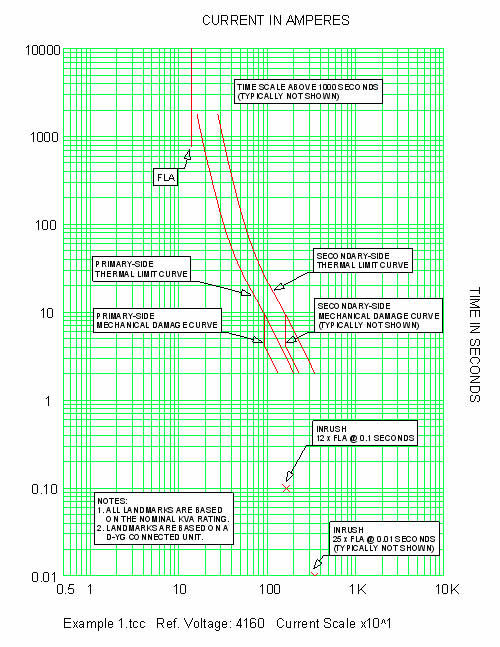
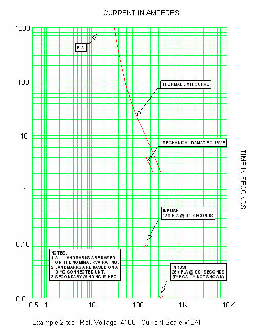
Magnetizing Inrush Current Point(s) One or more inrush current points may be plotted on a TCC. Inrush currents are expressed in peak amps. The most common point is 8-12 times rated FLA at 0.1 seconds. Another less common point is 25 times rated FLA at 0.01 seconds. Example 1 Plot the characteristic landmarks for a 1000kVA, 65°C, 4160-480/277V, Δ-YG, oil-filled, substation transformer with an impedance of 6.0%. Consider both the frequent and infrequent fault cases for this application. Solution Step 1 – Calculate the FLA FLA = 1000kVA / (1.732 x 4.16kV) = 139 amps Step 2 – Determine the Applicable Category This is a Category II transformer based on the nominal rating of 1000kVA Step 3 – Calculate the infrequent fault data points from Table 3 I 1800 sec = 2 x 139 amps = 278 amps Since the transformer is connected Δ-YG a separate set of data points must be calculated for primary-side protective devices. Primary-side devices will only see 58% of a secondary-side, single-line-to-ground fault. I 1800 sec = 0.58 x 2 x 139 amps = 161 amps Step 4 – Calculate the frequent fault data points from Table 3 I 2 sec = 139 amps / Z = 139 amps / 0.06 = 2316 amps Again, shift the data points by 0.58. I 2 sec = 0.58 x 139 amps / 0.06 = 1344 amps Step 5 – Calculate Inrush Points 12 x Inrush = 12 x 139 amps = 1668 amps The results are plotted in figure 1. Example 2 Repeat Example 1 but now assume the secondary is high-resistance grounded (HRG). Solution Step 1 – Same as Example 1 No shifting of the damage curve is required with a HRG secondary. In this case the primary-side protective devices will not see a ground fault on the secondary-side. Ground fault magnitudes will always be much lower than load current levels. Step 4 – Same as Example 1 Again, no shifting of data points is required. Step 5 – Same as Example 1 The results are plotted in figure 2. |
||||||||||||||||||||||||||||||||||||||||||||||||||||||||||||||||||||||||
 |
||||||||||||||||||||||||||||||||||||||||||||||||||||||||||||||||||||||||
| Fig. 1 1000kVA, Δ-YG, liquid-immersed transformer damage curves | ||||||||||||||||||||||||||||||||||||||||||||||||||||||||||||||||||||||||
 |
||||||||||||||||||||||||||||||||||||||||||||||||||||||||||||||||||||||||
| Fig. 2 1000kVA, Δ-YG (HRG), liquid-immersed transformer damage curves | ||||||||||||||||||||||||||||||||||||||||||||||||||||||||||||||||||||||||
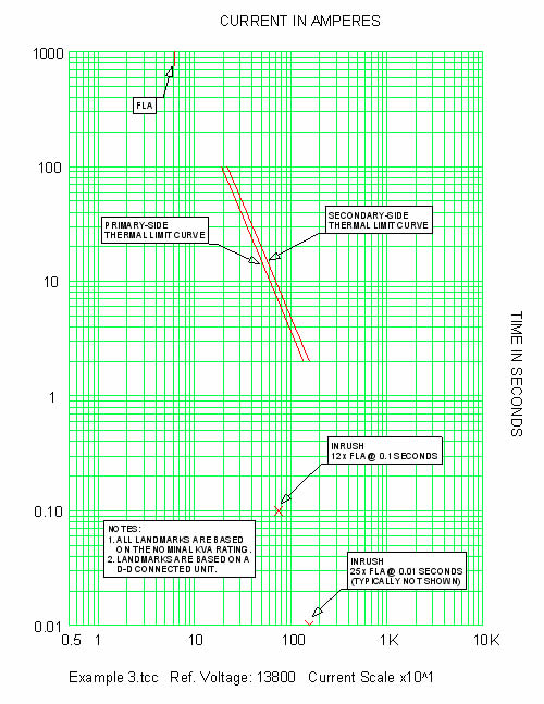
Example 3 Plot the characteristic landmarks for a 1500kVA, 150°C, 13800-480/277V, Δ-Δ, dry-type, substation transformer with an impedance of 5.75%. Consider the infrequent fault case for this application. Solution Step 1 – Calculate the FLA FLA = 1500kVA / (1.732 x 13.8kV) = 62.8 amps Step 2 – Determine the Applicable Category This is a dry-type, Category II transformer based on the nominal rating of 1500kVA Step 3 – Calculate the infrequent fault data points from Table 7 I 100 sec = 3.5 x 62.8 amps = 220 amps Since the transformer is connected Δ-Δ a separate set of data points must be calculated for primary-side protective devices. Primary-side devices will only see 87% of a secondary-side, line-to-line fault. I 100 sec = 0.87 x 3.5 x 62.8 amps = 191 amps Step 4 – Calculate Inrush Points 12 x Inrush = 12 x 62.8 amps = 754 amps The results are plotted in figure 3. |
||||||||||||||||||||||||||||||||||||||||||||||||||||||||||||||||||||||||
 |
||||||||||||||||||||||||||||||||||||||||||||||||||||||||||||||||||||||||
| Fig. 3 1500kVA, Δ- Δ, dry-type transformer damage curves | ||||||||||||||||||||||||||||||||||||||||||||||||||||||||||||||||||||||||
| References | ||||||||||||||||||||||||||||||||||||||||||||||||||||||||||||||||||||||||
| • Other Application Guides offered by SKM Systems Analysis at www.skm.com • ABB Protective Relaying Theory and Application, 2nd Edition, 2004 |
||||||||||||||||||||||||||||||||||||||||||||||||||||||||||||||||||||||||
| The latest revision of: | ||||||||||||||||||||||||||||||||||||||||||||||||||||||||||||||||||||||||
| • IEEE Std 242, IEEE Recommended Practice for Protection and Coordination of Industrial and Commercial Power Systems (IEEE Buff Book) • EEE Std C57.12.00, IEEE Standard General Requirements for Liquid-Immersed Distribution, Power and Regulating Transformers • IEEE Std C57.12.01, IEEE Standard General Requirements for Dry-Type Distribution and Power Transformers Including Those with Solid-Cast and/or Resin-Encapsulated Windings • IEEE Std C57.12.59, IEEE Guide for Dry-Type Transformer Through-Fault-Current Duration • IEEE Std C57.109, IEEE Guide for Liquid-Immersed Transformer Through-Fault-Current Duratio |
||||||||||||||||||||||||||||||||||||||||||||||||||||||||||||||||||||||||
| Insulating materials | ||||||||||||||||||||||||||||||||||||||||||||||||||||||||||||||||||||||||
|
||||||||||||||||||||||||||||||||||||||||||||||||||||||||||||||||||||||||
| back to Application guides | ||||||||||||||||||||||||||||||||||||||||||||||||||||||||||||||||||||||||