SKM Arc Flash Line Side vs. Load Side
The option of choosing the line-side or the load-side arc flash incident energy for arc flash labels is an important decision when performing an arc flash hazard analysis.
When an engineer performs an arc flash hazard analysis for any electrical equipment that includes a main overcurrent protection device (OCPD), there is a possibility of choosing between two distinct values of incident energies. They are referred to as the Line-Side or the Load-Side values. See Figures 1 and 2.
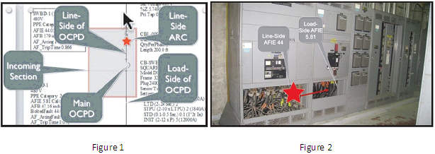
This choice could greatly affect the maintenance procedures of the electrical equipment. If the line-side incident energy - which is normally higher than the load-side incident energy - is chosen for the complete panel, the personal protective equipment (PPE) requirements would be more stringent than that required if the load-side incident energy was chosen.
When working on the incoming section of the enclosure (where the main OCPD is located), there could be an arc flash event on the line-side of this main OCPD. In this case, the electrician will be normally exposed to the higher incident energy value and he should be wearing higher rated PPE. When working on the feeder sections (on the load-side of the main OCPD), the electrician will normally be exposed to the lower incident energy value and could be wearing lower rated PPE. Nevertheless, you have to consider what would occur if the electrician is working on a feeder section adjacent to the incoming section. Normally, the arc flash is initiated by human error, but an arc flash event on the line-side could also occur while working on a feeder section (adjacent to the incoming section and without any human influence) due to insulation failure, lack of maintenance, overvoltages, animals, etc. Many switchboards and switchgears do not have strong and reliable barriers or isolation between the incoming section and the adjacent feeder sections. See Figure 3.
Therefore, if this arc flash event would occur on the line-side, the electrician working on the adjacent feeder section (protected only for lower load-side incident energy), he will probably be exposed to a higher incident energy than he is protected for. Therefore, which value of incident energy should be shown in the equipment arc flash label? There are many options for solving this issue. Three of them are the most common:
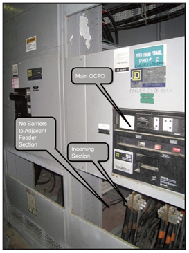
Figure 3
- Label the electrical equipment with only one incident energy value, the higher line side value. This will require the electrician to wear the highest rated PPE even while working on feeder sections at the load-side of the main OCPD.
- Label the equipment with a dual-value incident energy. One higher incident energy that applies only while working on the line-side of the main OCPD (the incoming section) an another lower value of incident energy while working on the load-side of the main OCPD (feeder sections). If the electrician is working on a feeder section adjacent to the incoming section of an open-framed switchboard, additional analysis should be performed to insure that the worker will be protected by the higher incident energy from the line-side that could migrate to the adjacent feeder section.
Note: The fact that an electrical equipment, where the main OCPD is installed, has a barrier that "seems strong enough" between the incoming section and the adjacent sections is not an acceptable condition to consider using dual-value incident energy arc flash labels. The engineer can't assume that an arc flash event on the line-side of the main OCPD will be totally contained (will not migrate to the adjacent sections). Therefore, under this circumstance, it is not acceptable to have an arc flash label with dual values, one for the incoming section and one for the rest of the switchgear.
Note: Only "arc-resistant" with "Suffix C" switchgears (applicable to low or medium voltage switchgears) built in compliance with ANSI/IEEE C37.20.7-2007 standard can insure that the dangerous power of the higher line-side incident energy from the incoming section will not migrate to the adjacent feeder section. Therefore, under this circumstance, it is acceptable to have an arc flash label with dual values, one for the incoming section and one for the rest of the switchgear. - Label the electrical equipment with only one incident energy value, the lower load-side value. This will require the electrician to wear the lower rated PPE even while working on the incoming section. According to the previous discussion, it is hard to understand why and engineer would choose to show the load-side value of incident energy on the label associated with the entire electrical equipment.
Why is the Line-Side and Load-Side Incident Energy Different?
The line-side incident energy value is normally higher than the load-side value because at the line-side the main OCPD is not involved in the clearing of the largest component of the arcing fault current. The main OCPD will only see the motor and generator contribution to the fault on the load-side of the main OCPD, which is normally much lower than the utility contribution to this fault and contributes the least amount of incident energy at that location. The OCPD that will interrupt the higher arcing current from the utility is upstream from this main OCPD and is normally is much larger. Higher ampere rated OCPD normally will result in longer interrupting time and therefore higher incident energies.
When is the Load-Side Incident Energy Higher than Line- Side Incident Energy?
There are, nevertheless, some few instances where the load-side incident energy is higher than the line-side incident energy. This might occur when there is a large motor contribution on the load-side bus. An example of this situation is shown on Figure 4, where we have several small motors (less than 50 HP) totaling 765 HP modeled as a single equivalent motor connected directly to the bus of a motor control center (MCC). Under these conditions, the load-side incident energy is more than twice as large as the lineside incident energy.
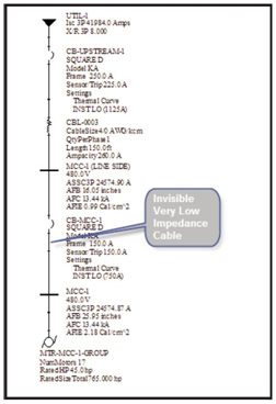
Figure 4
Modeling the Line-Side vs. Load-Side option in the Arc-Flash module of SKM Power*Tools for Windows software
One possible option to model the load-side vs. line-side incident energy is shown in Figure 4. Place a bus immediately upstream from the main OCPD. You could rename this bus with the name of the electrical equipment and add some indication that shows that this bus is the line-side bus. In Figure 4 the line-side bus is designated as "MCC-1 (LINE SIDE)". We want the load-side of this main OCPD to be connected directly to the bus of the electrical equipment. In Figure 4 that bus would be MCC-1. But in the Power*Tools software we can't have an OCPD connected directly between two buses without an impedance. To solve this challenge, we can insert a non-existing impedance (cable) between the load-side of the main OCPD and the equipment bus. This cable does not exist, so it should be modeled with very low impedance and it's symbol should be changed to show just a line (See Figure 4). Now you can calculate the line-side incident energy and the load-side incident energy by using the Arc Flash software module and use the options as shown in Figure 5.
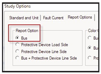
Figure 5
After the Arc-Flash module finishes the calculations, the results table will show the load-side incident energy at bus MCC-1 (2.2 cal/cm^2) and the line-side incident energy (0.99 cal/cm^2). See Figure 6.
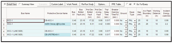
Figure 6
In this particular case the label attached to the equipment should show the higher incident energy calculated for the load-side bus.
Conclusions
- When any electrical equipment has a main OCPD, there are two levels of incident energy, one at the line-side of the main OCPD and one at the load-side.
- Normally, the line-side incident energy is equal or larger than the load-side incident energy. There are few instances where the load-side incident energy is higher than the line-side incident energy.
- The majority of the electrical equipment are not Arc-Rated tested to accepted standards.
- If electrical equipment is not Arc Rated according to recognize standards (that insures the containment of the arc flash energy in the faulted section without any migration of energy to the adjacent sections) we do not have any guarantee that this migration will not happen, even when barriers exist between adjacent sections.
- Every electrical equipment that has a main OCPD could be modeled in Power*Tools for Windows as having a line-side bus and a load-side bus and perform the arc flash calculation in both locations.
- Under normal circumstances, the consultant performing the arc flash hazard analysis should print the label for this equipment with the higher incident energy.
- There are some exceptions to this general rule, but these exceptions should be analyzed with care, considering maintenance procedures that would justify that decision.